B
ber5ien
New member
- Joined
- 25.03.2024
- Messages
- 27
- Reaction score
- 5
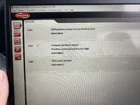
I have constant problems with the EGR system. The car goes into limp mode. In winter everything was fine. In hot weather for some reason everything gets worse.
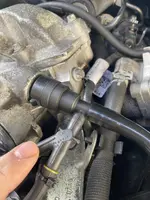
Replaced the back pressure sensor with a new one (OEM Mercedes).
Replaced cable to back pressure sensor (OEM Mercedes).
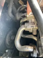
Replaced the EGR with an aftermarket one (no changes), installed the original back in (Mercedes OEM).
The mechanic checked the EGR, it opens/closes.
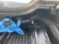
There were cracks in the rubber of the EGR pressure valve. This was fixed, but I probably did it myself during troubleshooting.
Checked the intake system with smoke (no problems, no leaks, all seals/gaskets are OK).
The car is a Mercedes R-Class 2011 OM642 350 CDI 263.
I suspect the cable that connects to the EGR is damaged, but I don't have any diagrams and I'm not sure what exactly to check.
Any ideas would be great.
Download attachments

