B
ber5ien
New member
- Joined
- 25.03.2024
- Messages
- 27
- Reaction score
- 5
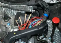
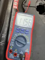
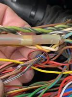
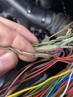
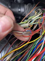
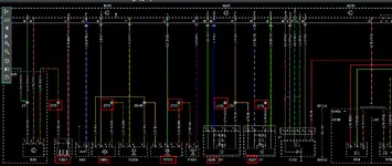
I checked the connector with the rear probe with the ignition on.
I think I should expect two 12V cables or at least one.
Is there a short circuit somewhere?
5 pin 533mV
4 pin 0.8mV
3 pin 5V
2 pin 261mV
1 pin 261mV
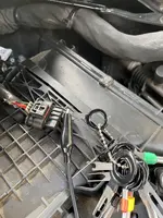
Disconnected plug:
5 pin 4.1V
4 pin 8mV
3 pin 5V
2 pin 12+V
1 pin 32mV
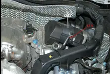
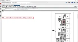
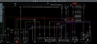
I checked the EGR ground again and found that the positive battery terminal had 12V so the ground was good.
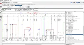
I think I should expect two 12V cables or at least one.
Is there a short circuit somewhere?
5 pin 533mV
4 pin 0.8mV
3 pin 5V
2 pin 261mV
1 pin 261mV
Disconnected plug:
5 pin 4.1V
4 pin 8mV
3 pin 5V
2 pin 12+V
1 pin 32mV
I checked the EGR ground again and found that the positive battery terminal had 12V so the ground was good.